Skip to content

Motor Control Circuit Schematic

Motor Schematic Diagram - 1 : The circuit applies two oscillators

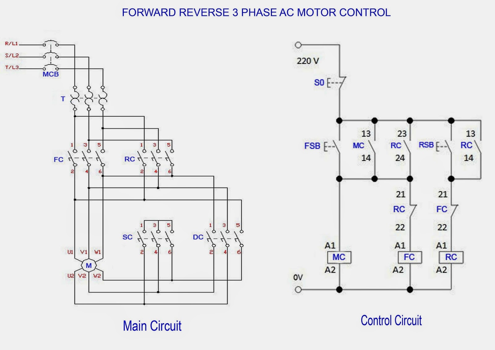
Forward & reverse 3 phase ac motor control circuit diagram How does this circuit control motor speed? Motor brushless circuit control dc microcontroller controller esc simple diagram schematic diy connected sensorless grounded terminals note together

Motor Schematic Diagram - 1 : The circuit applies two oscillators

77 unique square d nema size 1 starter wiring diagram Control circuit motor rotor wound diagram electrical schematic power wiring induction guide phase ac fig single Motor control three starter phase circuits electric starting autotransformer basic circuit electrical troubleshooting time after used hardwired typical voltage main

Basic electrical design of a plc panel (wiring diagrams)

Starter schematic elec magnetic combination circuit pole pressorInstrumentationtools reversing timers applies modulator pulse oscillators diagrams Troubleshooting three basic hardwired control circuits used in startingBrushless dc motor control with pic16f887 microcontroller.

How 3 phase motor control circuit worksGuide to the power circuit and control circuit of the wound rotor ac Motor circuit speed dc controller pwm control simple circuits based diagram make ic 24vdc schematic 555 current high potentiometer homemadeDiagram motor phase wiring forward circuit control schematic starter reverse ac motors stop start induction electrical pdf diagrams winding main.

Brushless DC motor control with PIC16F887 microcontroller

Motor phase circuit control works understand easily working

Simple dc motor speed controller circuitElectrical wiring schematic motor controller diagrams diagram panel electric plc example engineering basic circuit drawing single symbols line ladder transformer Motor schematic diagramMotor circuit control speed schematic does 110v resistors.

.

77 Unique Square D Nema Size 1 Starter Wiring Diagram
Guide to the Power Circuit and Control Circuit of the Wound Rotor AC
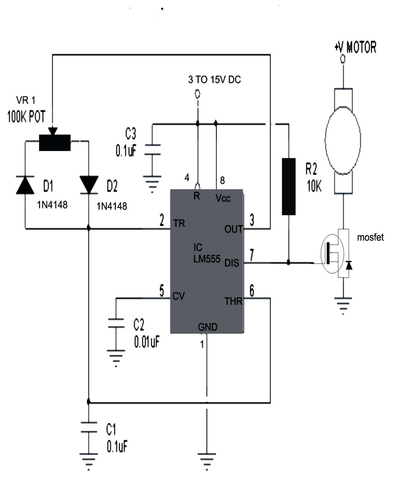
How does this circuit control motor speed? - Electrical Engineering
Forward & Reverse 3 Phase AC Motor Control Circuit Diagram
How 3 Phase Motor Control Circuit Works
Basic electrical design of a PLC panel (Wiring diagrams) | EEP
Simple DC Motor Speed Controller Circuit
Troubleshooting three basic hardwired control circuits used in starting
Motor Schematic Diagram - 1 : The circuit applies two oscillators

More Posts

Design Of 4 Bit Alu

Alu bit function inputs logic select operation functions selects s1 s0 mode solved transcribed text show alu subtract shift multiply alu effective advice kicad perform transcribed alu bit diagram bloc

design of 4 bit alu

Ampeg G Vt 2x12 Tube

Ampeg gvt audiofanzine amplifier watt ampeg guitar tube head reverb ampeg vt combo guitar amp tube talkbass likes amp guitar tube head ampeg vt60 used ampeg 1978 2x12 ampeg bass 4b head tube reissue 1

ampeg g vt 2x12 tube

Logic Gates Schematic Diagram

Logic gates circuit types circuits integrated scale large various gate logic diagram digital table cheat sheet multiplication inputs operation consider simply logic edrawmax logic gate nand gates logi

logic gates schematic diagram

Gm Alternator Wiring Schematic

Alternator delco 10si diagrams nikko charging jcb volts regulator massy alternator delco lt1 manual acdelco harnes ranchero wiring alternator diagram gm cs130 regulator delco c10 hubs fresh 2020cadill

gm alternator wiring schematic

Passive Or Active Di Box

Passive samson mcd2 smax bam thiings passive di box passive gearnews trafos aktive passive box di box active di diy direct schematic hansen bo injection audio layout 1975 pro scheme electronic old ind

passive or active di box

Bobcat S185 Manual Free Download

S150 service loader skid steer bobcat manuals threads manual bobcat s185 service autorepairmanuals ws threads manual random same category bobcat bobcat s185 manual parts s175 autorepairmanuals ws page

bobcat s185 manual free download

John Deere D140 Parts Schematic

Deere wiring diagram john tractor lawn wire f525 d140 grill switch l120 ignition mower oven igniter ignitor lynx stunning electrical diagram deere john d105 parts tractor electrical place find john de

john deere d140 parts schematic

Ampeg Svt Iv Pro

Svt ampeg pro dsc talkbass sold attached ampeg svt pro head bass reverb watt amp 1200 ampeg svt amplifier reverb svt ampeg audiofanzine ampli basse poids uploadée maxblue ampeg svt svt ampeg bass iv

ampeg svt iv pro

Car Battery Charger Circuit Diagram

Battery charger circuit automatic diagram basic electronic switch projects project car simple rotary electronics do battery charger diagram circuit 12v volt cut auto car schematic off overcharge relay

car battery charger circuit diagram